How Can We Help?
-
Controllers
-
- Pro-160 / 360 Fault Codes
- Pro-160 / 360 Temperature Sensors
- Pro-100 / 160 / 360 to Hall Throttle Wiring
- JSK-120 Driving Two Pro-360s
- RBT and Pro-160 / 360 P3 Pot Fault
- Pro-160 / 360 Dual Control
- Pro-100 / 160 / 360 Radio Control Failsafe
- Pro-100 / 160 / 360 to JSK-100 wiring
- Pro-100 / 160 / 360 Failsafe Contactor
- Double Heading the Pro-100 / 160 / 360
- Pro-160 Layout Diagrams
- Pro-100 / 160 / 360 Software Versions
- Use with shunt wound motors
- Use with Series Wound Motors
- Updating Firmware
- Double Heading Pro-160 / 360 & 4QD Series
- Push Button Mode With Limit Switches.
- Pro-100 / 160 / 360 Troubleshooting
- Speed Sensor Ratio
- Push Button - Forward / Off / Reverse Operation
- Show Remaining Articles (5) Collapse Articles
-
- Pro-160 / 360 Fault Codes
- Pro-160 / 360 Temperature Sensors
- Pro-360 Heatsink Removal and Replacement
- Pro-100 / 160 / 360 to Hall Throttle Wiring
- JSK-120 Driving Two Pro-360s
- RBT and Pro-160 / 360 P3 Pot Fault
- Pro-160 / 360 Dual Control
- Pro-100 / 160 / 360 Radio Control Failsafe
- Pro-100 / 160 / 360 to JSK-100 wiring
- Pro-100 / 160 / 360 Failsafe Contactor
- Double Heading the Pro-100 / 160 / 360
- Pro-100 / 160 / 360 Software Versions
- Updating Firmware
- Use with shunt wound motors
- Use with Series Wound Motors
- Double Heading Pro-160 / 360 & 4QD Series
- Push Button Mode With Limit Switches.
- Pro-100 / 160 / 360 Troubleshooting
- Pro-360 Locknut Service Bulletin
- Speed Sensor Ratio
- Push Button - Forward / Off / Reverse Operation
- Show Remaining Articles (6) Collapse Articles
-
- Pro-100 Fault Codes
- Pro-100 / 160 / 360 to Hall Throttle Wiring
- RBT and Pro-160 / 360 P3 Pot Fault
- Pro-160 / 360 Dual Control
- Pro-100 / 160 / 360 Radio Control Failsafe
- Pro-100 / 160 / 360 to JSK-100 wiring
- Pro-100 / 160 / 360 Failsafe Contactor
- Double Heading the Pro-100 / 160 / 360
- Pro-100 / 160 / 360 Software Versions
- Updating Firmware
- Use with shunt wound motors
- Use with Series Wound Motors
- Pro-100 / 160 / 360 Troubleshooting
- Speed Sensor Ratio
- Push Button - Forward / Off / Reverse Operation
-
- Mosfet Insulator Arrangement DNO & Porter
- How To Wire Up a Porter 5
- Closed Loop Current Control
- Fitting a Porter to a PDQ Power trike
- Driving the Porter by Raspberry Pi
- Porter: Disabling Regenerative Braking
- Porter Current Limit Adjustment
- DMR-203 Radio Control of a Porter 5 / 10
- Porter 40 Speed Controller
- Porter 40: Use with PWM Input
- Porter Troubleshooting
-
-
- PRO-150 Overview
- Double Heading for the Pro-150 and 4QD Series
- Pro-150 Hall Throttle Supply
- Pro-150 Hall Throttle Programming
- Pro-150 Push Button Use
- Use with shunt wound motors
- Pro-150 Fault Finding Guide
- Pro-150 Pt Fault Code
- Pro-150 programmable parameters
- Pro-150 Mechanical Information
- Pro-150 Basic Wiring Diagram
- Fraser Golf Buggies, Wiring for Pro-150
- DMR-203: Use with PRO-150 Controllers
- Pro-150 Capacitor Modification
- PRO-150 Current Limit
- PRO-150 Issue History
- PRO-150 Joystick Programming
- Show Remaining Articles (2) Collapse Articles
-
- 4QD-200/300 Overview
- Double Heading for the Pro-150 and 4QD Series
- Control Board Jumper Positions
- Ampflow motor
- Damage From Blown Mosfets
- DMR-203: Use with 4QD Series Controllers
- Battery Contactor for 4QD-200 / 300
- Adjustment for 48V
- Inhibit switch / footbrake - 4QD series only [tour 16]
- Forward / Off / Reverse Mode (4QD Series)
- Converting Parking Brake to Brake Light
- Disabling HPLO on Early 4QD Models
- Inhibit Ramp Modification [4QD series]
- Over voltage protection in the 4QD series
- Deadband values and removal
- How to dismantle the 4QD series
- Fault finding on the 4QD series
- Testing the 4QD Base Board and MOSFETs
- Reverse Acceptance Threshold [RAT] Modification
- Current limit resistors
- Use with Tacho Feedback Board
- Control Board Modification [Pre June 2010]
- Reverse Speed Modification [pre issue 17]
- Reversing Latch Modification [pre issue 16]
- Damage from a Reversed Battery (4QD Series)
- Mixing 4QD 150 / 200 / 300 series boards
- 4QD version history
- Inhibit
- Show Remaining Articles (13) Collapse Articles
-
- Damage from Reversed Batteries (NCC/VTX)
- Waveforms and Fault Finding
- Ramp Timings (NCC)
- Internal Power Supply and Protection Circuitry
- Fitting Expansion Connector
- NCC Speed Controller
- VTX and NCC Operating Voltages
- NCC Circuit Description
- VTX / NCC Fault Finding
- NCC Mark 2 Issue Number History
- NCC Mark 1 Issue Number History
- NCC Key Components
- NCC Zener Diode Failure
-
- Internal Power Supply and Protection Circuitry
- Current Limiting in the Pro-120 [and others]
- Pro-120 Mk1 History
- Pro-120 Mk2 History
- Pro-120 Key Components
- Earth Fuses: Why Do They Blow?
- Modifying the Pro-120 for other voltages
- Pro-120 Fault Finding Tips
- PRO-120: Multiple Slaves
- PRO-120 Ramp Reduction
- Fitting Expansion Connector
- Pro-120 Modification to give Uni-Directional Control
- Pro-120 Robot Wars Version
- Pro-120 Ignition Options
- Battery Discharge Protection: PRO-120
- Pro 120 Mark 1 Speed Controller
- PRO 120 Mark 1 - Additional Diagrams
- Show Remaining Articles (2) Collapse Articles
-
-
-
Accessories
-
-
- Articles coming soon
-
- Articles coming soon
-
- Articles coming soon
-
- Articles coming soon
-
- Articles coming soon
-
- Articles coming soon
-
Application Notes
-
- Alternative Double Heading [MU] Solution
- Double Ended Tram Control
- Loco Wiring: Auto Reversing Lights
- Speed to RPM Calculator
- Noise Suppression for Multiple Motors
- DCC / Airwire Interface
- Phoenix Loco Wiring
- Loco Wiring: Hand Control & Horn Relay Board
- Double Heading Problems
- Motors in Parallel
- Basic Model Loco Installation [with RBT and HRB]
- Low Pulling Power
- Radio Control
-
-
-
Technical
-
- Speed to RPM Calculator
- Noise Suppression for Multiple Motors
- Improving Heat Dissipation
- A Basic Installation
- Motor Noise Suppression
- Catching diodes
- Multi speed control
- Parking Brakes in Series
- Fuses and Circuit Breakers
- Radio Control Wiring Hints
- Typical Wiring for the PRO-150, DNO, VTX and NCC Controllers
- Wiring for Hand Control and Radio Control
- Wiring for Push Button Use
- Good Wiring Practise
- Motors in Parallel
- Push Button Mode With Limit Switches.
- Forward / off / reverse mode or push-button operation
- Basic Model Loco Installation [with RBT and HRB]
- Pro-100 / 160 / 360 to Hall Throttle Wiring
- How do I select the parts?
- Use With Switch Mode Power Supplies
- Push Button - Forward / Off / Reverse Operation
- Wiring for Curtis ET-126MCU
- Radio Control
- DIN Socket Wiring
- Show Remaining Articles (10) Collapse Articles
-
- Current limit
- PCB numbers
- Acceleration and Deceleration Ramps
- Thermal shutdown
- Ignition
- Power down state
- Ramps
- Reversing
- Overvoltage protection
- Battery Discharge Protection
- Joystick [aka wig-wag]
- Parking brake driver
- Pot Fault Detection
- High Pot Lockout HPLO
- Reverse polarity protection [tour 26]
- Main Capacitor
- Radio control interface
- Tacho Generator Feedback
- Voltage Following
- What Does a Motor Speed Controller Do?
- Ignition Circuit
- Coulomb Counting
- Show Remaining Articles (7) Collapse Articles
-
- Using a BMS with a Motor Controller
- Mosfet Alternatives
- Testing an Electric Motor
- What is EMC [Electromagnetic Compatibility]?
- Closed Loop Current Control
- Battery Current and Motor Current
- MOSFETs
- Half bridge
- Switching frequency
- What is Regenerative Braking?
- Batteries
- Customised Arc Potentiometers
- What is PWM Motor Control
- Full Bridge
- Towing
- Torque
- Surge Currents
- Speed Stability
- Quadrants
- Heat
- Thermal shutdown
- Heatsinking
- Choosing a Controller
- Earth Track Fuse and Earth Loops
- Tacho Set-Up
- Charging a 24V Battery From a 12V Source
- What Voltage Should I Use? [12, 24, 36, or 48V]
- Positional Servo Control [DNO / VTX]
- POT Dead Band
- Why Do Mosfets Fail?
- Back EMF & Internal Resistance
- Use of Generators with Speed Controllers
- Control by Microprocessor
- Foot Pedal Idea
- Coulomb Counting
- Low Pulling Power
- Curtis Equivalents
- Show Remaining Articles (22) Collapse Articles
-
Horn Relay Board Circuit Diagram and Layout
This page has the circuit diagram and board layout for our horn relay board.
Circuit diagram:
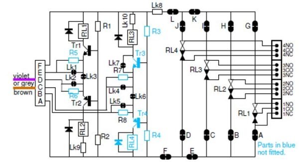
Operation
A six way input connector is fitted, although normally only two pins [C & D] are used. The extra four pins are provided to add to the board’s versatility.
( ) indicates that the connection is not normally used
[ ] indicates alternative function which may be obtained by altering the board.
| Pin | Purpose | Alternative Use |
| A | (Battery negative) | |
| B | RL3 | [RL4] |
| C | RL3 | |
| D | RL2 and RL1 | [RL2] |
| E | RL2 and RL1 | [RL1] |
| F | (Battery positive) |
RL1 and RL2 are operated via a single wire to either input pin E or pin D. Two pins are used so it is possible to split operation and have the relays operating separately (not a feature of the standard board).
Connecting one of these pins to B- (battery -ve) operates RL1 and connecting it to B+ (Battery +ve) operates RL2.
Connecting pin C or B to Battery – operates RL3.
Board layout – Underside: Note location of link K in red.

Board layout – Topside:
